Engineering Methodology • Independent Technical Publication
Core Premise: What Should Each Design Option Help the Team Learn?

Explore More Than One Design Direction Before Committing.

Follow practical engineering cases about parallel concepts, changing constraints, design trade-offs, comparison questions, and convergence decisions.

Methodology Schema Parallel Cycle
01

Starting Constraint

Define non-negotiable boundaries, envelopes, and operational limits.

02

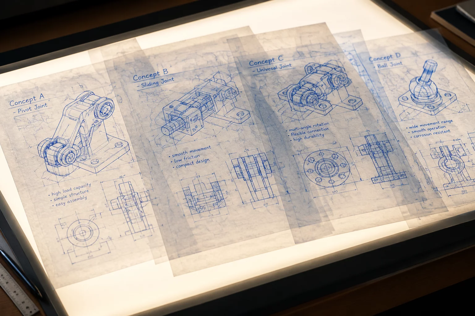
Option A / B / C

Branch into bounded concept paths to isolate distinct structural approaches.

03

What Changed

Identify which geometric or structural decisions actually differ.

04

What We Learned

Record what improved and which new compromise appeared.

05

Convergence Question

Synthesize learnings before locking CAD trees and production tooling.

Request Engineering Insights

Get the latest parallel design case studies and evaluation matrices directly.

Empirical Engineering Impact

Proven Methodologies Across Hardware Teams

Documented metrics from parallel branch explorations, trade-off matrices, and structured design convergence cycles across prototype labs and hardware startups.

[ 01 ]
8+

Years of Active Research

Independent mechanical engineering research, trade-off documentation, and continuous curriculum development.

[ 02 ]
140+

Option Forks Documented

Real-world mechanical branches analyzed from initial constraint definition to clear convergence questions.

[ 03 ]
85+

Hardware Teams Guided

Prototype labs, robotics collectives, and product-development groups adopting structured exploration frameworks.

[ 04 ]
42%

Faster Convergence

Average reduction in rework loops before committing to single-path production tooling and assembly.

Engineering Cost Analysis

Costly Engineering Pitfalls of Early Convergence

When hardware teams commit to a single CAD concept prematurely, hidden assembly collisions, tooling revisions, and unexamined trade-offs compound down the line. Discover why linear progression fails complex mechanical products.

ERR-01 • TOOLING High Risk

Linear CAD Lock-In Before Envelope Check

Rushing straight into parametric detail modeling around a single component arrangement without parallel kinematic checks. Teams optimize brackets for weeks before discovering tooling bit clearance is physically blocked.

Average Iteration Cost +$18,500 / Tool Recut
Schedule Slippage 4 to 7 Weeks
ERR-02 • ASSEMBLY Critical

The Compactness Illusion Over Fastener Access

Minimizing external enclosure dimensions at the expense of tool entry trajectories. Prototypes assemble smoothly by hand on open benches, but production line throughput drops due to blind-fastener torquing.

Cycle Time Penalty +210s per Unit
Scrap & Rework Rate 14.2% in Pilot Run
ERR-03 • WORKFLOW Knowledge Loss

Discarding Concepts Without Synthesizing Trade-Offs

Abandoning secondary concept models without documenting what failed and why. When manufacturing vendor constraints shift two months later, the team re-debates the exact same unrecorded mechanics.

Duplicated R&D Effort ~80 Engineering Hours
Team Alignment Cost High Friction
[Interactive Dilemma Matrix]

Identify Your Current Engineering Bottleneck

When an engineering path hits friction, committing too early creates technical debt. Select your primary design tension below to inspect the parallel branch strategy, trade-off dynamics, and convergence guidance.

Starting Constraint

Packaging Volume Limit

The overall outer dimension cannot grow, yet internal motor wattage and wire routing need 18% additional volume clearance.

What This Forces:

Testing structural chassis integration versus stacked modular subassemblies.

Risk of Single-Path:

Forcing the primary concept into a miniature unibody leads to thermal traps.

3-Way Concept Split

Parallel Exploration Vectors

Option Fork A

Unibody Skeleton

Direct bearing pockets machined into external structural skin.

Option Fork B

Folded Sheet Core

Internal stamped bracket with snap-on perimeter non-structural shields.

Option Fork C

Symmetrical Split

Two identical clamshell halves sharing fastener bosses symmetrically.

Convergence QuestionAnalysis Phase

Does the unibody stiffness gain justify a 35% higher tooling setup cost compared to folded sheet brackets?

Common Friction: “We cannot afford parallel CAD models for small changes.”

Option forks do not mean full production detailing. You build lightweight constraint sketches just far enough to calculate volume interference before committing master geometry.

Starting Constraint

Z-Axis Build Stack

Assembly operators currently require rotating the chassis across 4 orientations to insert internal gear shafts and retaining clips.

What This Forces:

Designing a top-down single-direction drop-in architecture.

Risk of Single-Path:

Optimizing strictly for assembly may balloon component part counts and tolerance stackups.

3-Way Concept Split

Parallel Exploration Vectors

Option Fork A

Cartridge Cassette

Pre-assembled gear train inserted as a self-contained dropped cassette.

Option Fork B

Integral Retainers

Snap-fit cantilever fingers replacing separate circlips and washers.

Option Fork C

Split Datum Ribs

Base chassis with open locating slots closed by a single clamping plate.

Convergence QuestionSynthesis Check

Which option reduces total takt time without introducing secondary tolerance stack issues across temperature shifts?

Common Friction: “Modular cassettes add extra outer housing walls.”

Testing the cassette fork against the integral chassis fork immediately surfaces whether the line speed gain compensates for the added wall thickness.

Starting Constraint

Line-of-Sight Clearance

Calibration potentiometers and primary structural screws are shadowed by secondary cable routing harness brackets.

What This Forces:

Re-orienting fastening axes or creating unobstructed service access tunnels.

Risk of Single-Path:

Relocating fasteners without branch review can weaken load-bearing perimeter joints.

3-Way Concept Split

Parallel Exploration Vectors

Option Fork A

External Flange

Moving fastener bosses outside the seal perimeter for direct straight bit reach.

Option Fork B

Hinged Swing Bay

Harness tray pivots out on a retained captive hinge pin during repair.

Option Fork C

Keyhole Locking

Twist-lock mechanical bay requiring zero tools for routine harness service.

Convergence QuestionField Evaluation

Does external flange fastening satisfy IP ingress ratings while meeting technician maintenance window targets?

Common Friction: “External screws ruin industrial design aesthetics.”

Exploring the hinged bay in parallel allows the team to contrast industrial design elegance against pure field service speed before committing tooling.

Starting Constraint

Mid-Flight Spec Delta

Product requirements updated to mandate passive heat dissipation for an upgraded 45W compute board mid-prototype cycle.

What This Forces:

Re-opening the thermal boundary without scrapping the baseline drive system.

Risk of Single-Path:

Patching heatsinks onto an unverified chassis creates unmaintainable custom brackets.

3-Way Concept Split

Parallel Exploration Vectors

Option Fork A

Chassis Heat Sink

Conductive thermal pad directly coupling PCB back to die-cast bottom plate.

Option Fork B

Chimney Flow Fin

Vertical convective channels integrated into rear decorative vents.

Option Fork C

Heat Pipe Offset

Sintered copper pipe routing thermal load to existing external perimeter ring.

Convergence QuestionDecision Gate

Can thermal conduction through the cast base prevent adding secondary internal airflow fans?

Common Friction: “Reopening a design mid-schedule causes fatal project delays.”

Structured option forks allow you to timebox parallel concept evaluation to 48 hours, yielding hard physical answers before the gate review.

01 / STARTING CONSTRAINTS

WHY EXPLORATION MUST DIVERGE

In mechanical development, pushing a single primary concept past its early limits often hides secondary penalties. When a baseline requirement creates assembly friction or packaging gridlock, opening structured parallel paths reveals what each direction can teach the team before committing tooling.

CORE CONVERGENCE GOAL
Identify trade-offs before CAD freeze
CASE STUDY ANALYSIS SYSTEM CRITICALITY: HIGH

THE COMPACT ENCLOSURE FORK

When the external product envelope was reduced by 18%, the single nominal CAD path routed internal wiring through tight thermal conduits, multiplying assembly time. Rather than patching cable clips, the team opened three parallel explorations: Option A (integrated rigid-flex harness), Option B (split modular chassis), and Option C (reoriented motor stack).

-18% Envelope Volume
3 Paths Parallel Forks
1 Freeze Informed Decision
What The Team Learned: The split chassis provided 80% of the harness routing benefit without the expensive tooling penalty of custom rigid-flex circuits.
CASE STUDY ANALYSIS SYSTEM CRITICALITY: MEDIUM

THE HIDDEN FASTENER FORK

Deeply nested hex screws guaranteed clean aesthetic surfaces but required custom ball-end torque wrenches on the assembly line. Two branches emerged: Option A sacrificed one clean face for top-accessible fastener ports, while Option B moved to slide-and-lock internal interlocking rails.

4.5 min Baseline Cycle Time
1.2 min Target Cycle Time
0 Custom Specialty Tools
What The Team Learned: Interlocking rails eliminated 6 fasteners entirely, rendering tool clearance trade-offs irrelevant.
CASE STUDY ANALYSIS SYSTEM CRITICALITY: CRITICAL

THE PROCESS CONVERSION FORK

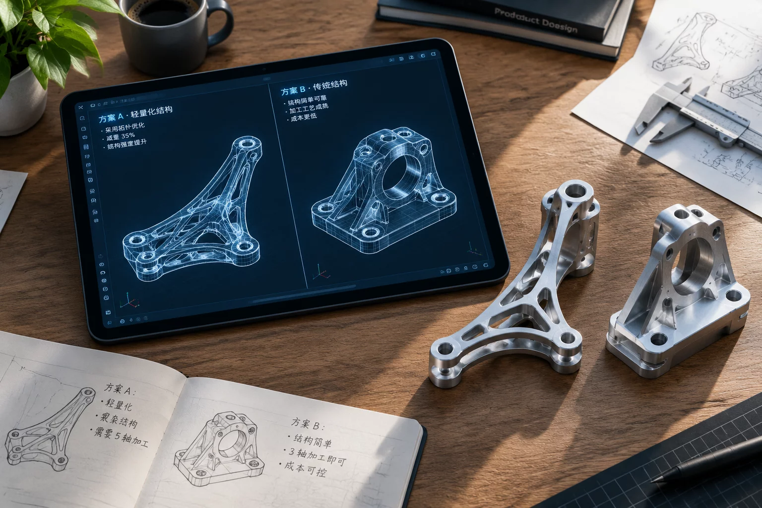
Early structural tests validated a 5-axis CNC unibody bracket, but projected production quantities made machining cost-prohibitive. The fork split into: Option A (hybrid welded sheet-metal subassembly) and Option B (die-cast aluminum bracket with post-machined datum planes).

$142 Nominal CNC Unit Cost
$28 Die-Cast Unit Cost
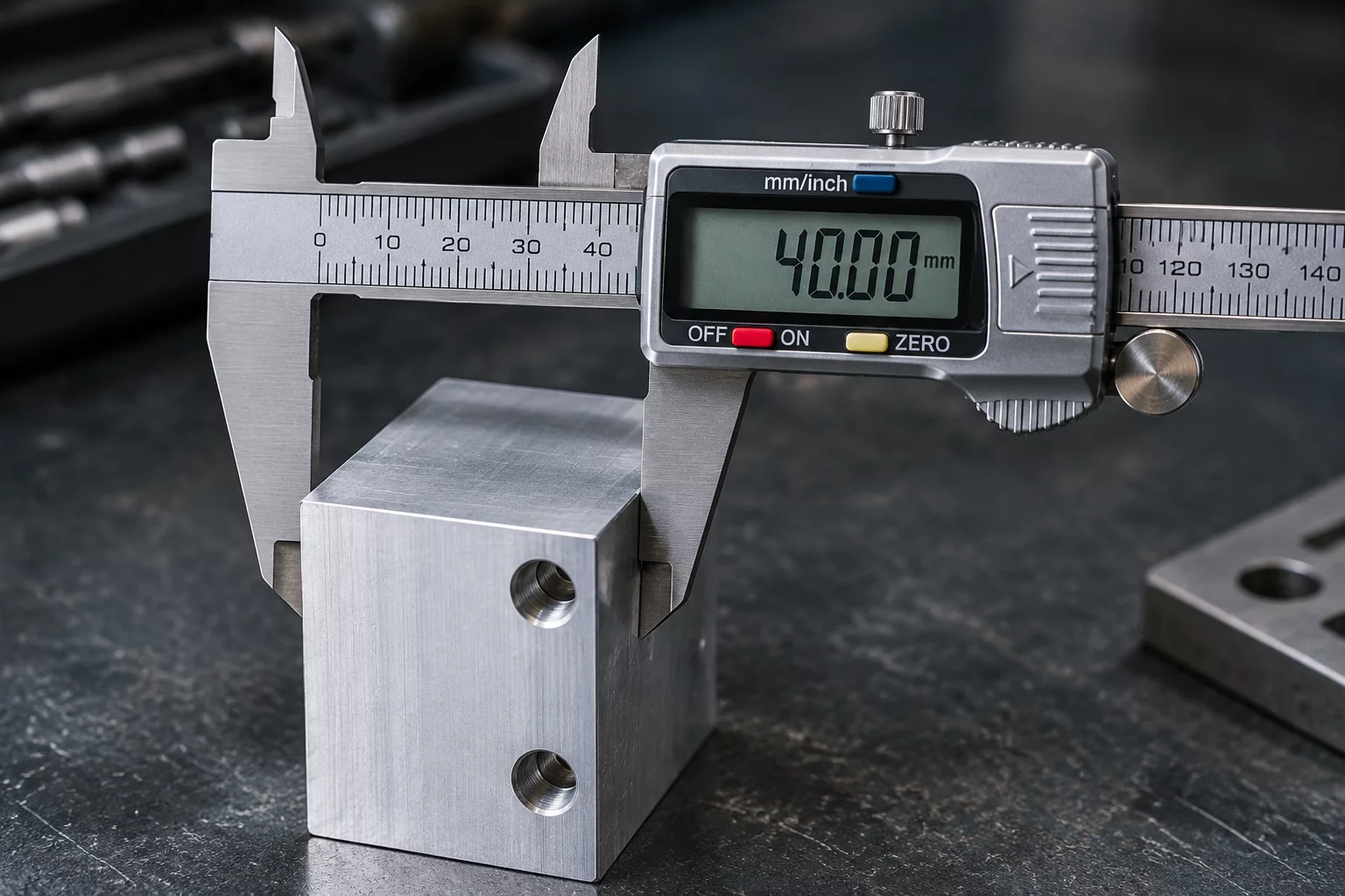
±0.05mm Tolerance Retained
What The Team Learned: Post-machining only three key mounting datums kept die-cast parts within tight optical tolerances at a fraction of unibody cost.
CASE STUDY ANALYSIS SYSTEM CRITICALITY: MEDIUM

THE SERVICEABILITY DILEMMA

Epoxy-bonded cross members maxed out torsional stiffness under load testing, but replacing a worn belt drive required destroying the chassis shell. Fork branches weighed removable truss plates against oversized bearing cartridges with a 50,000-hour mean time before failure.

50k hrs Bearing Lifespan
98% Stiffness Preserved
< 15 min Field Swap Time
What The Team Learned: A bolt-on truss with dowel pin locators preserved torsional stiffness while maintaining 15-minute field serviceability.
Parallel Concepts

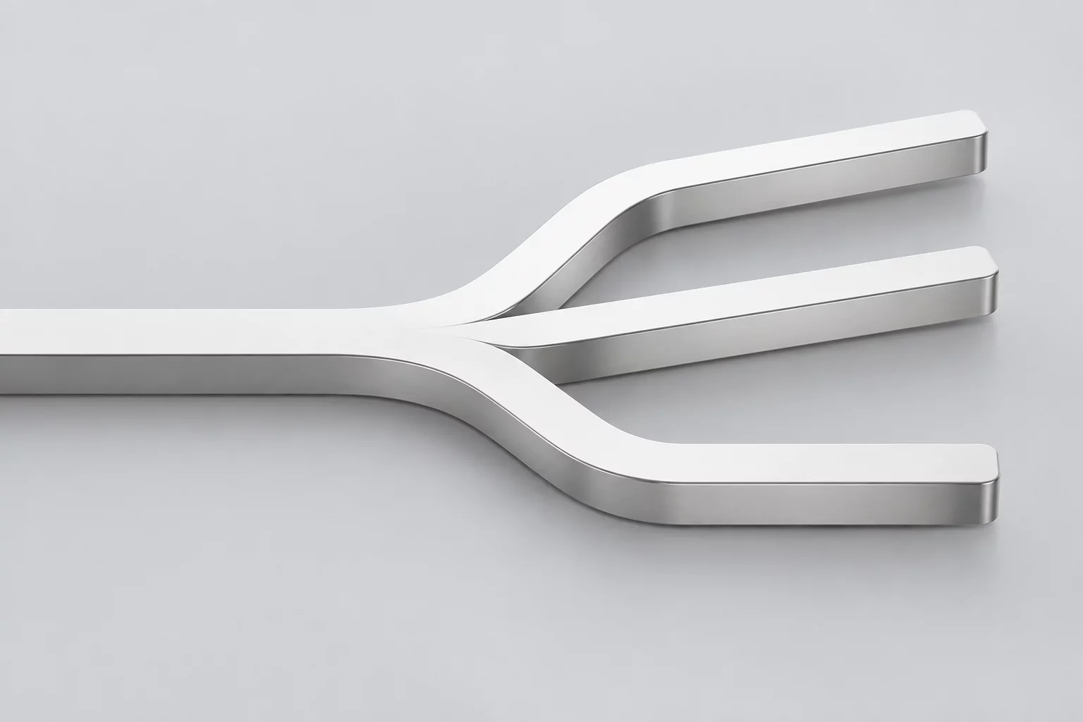
Parallel Concept Branches for Single Constraints

Active Challenge

Compact Desktop Mechanism Enclosure

01
What Changed

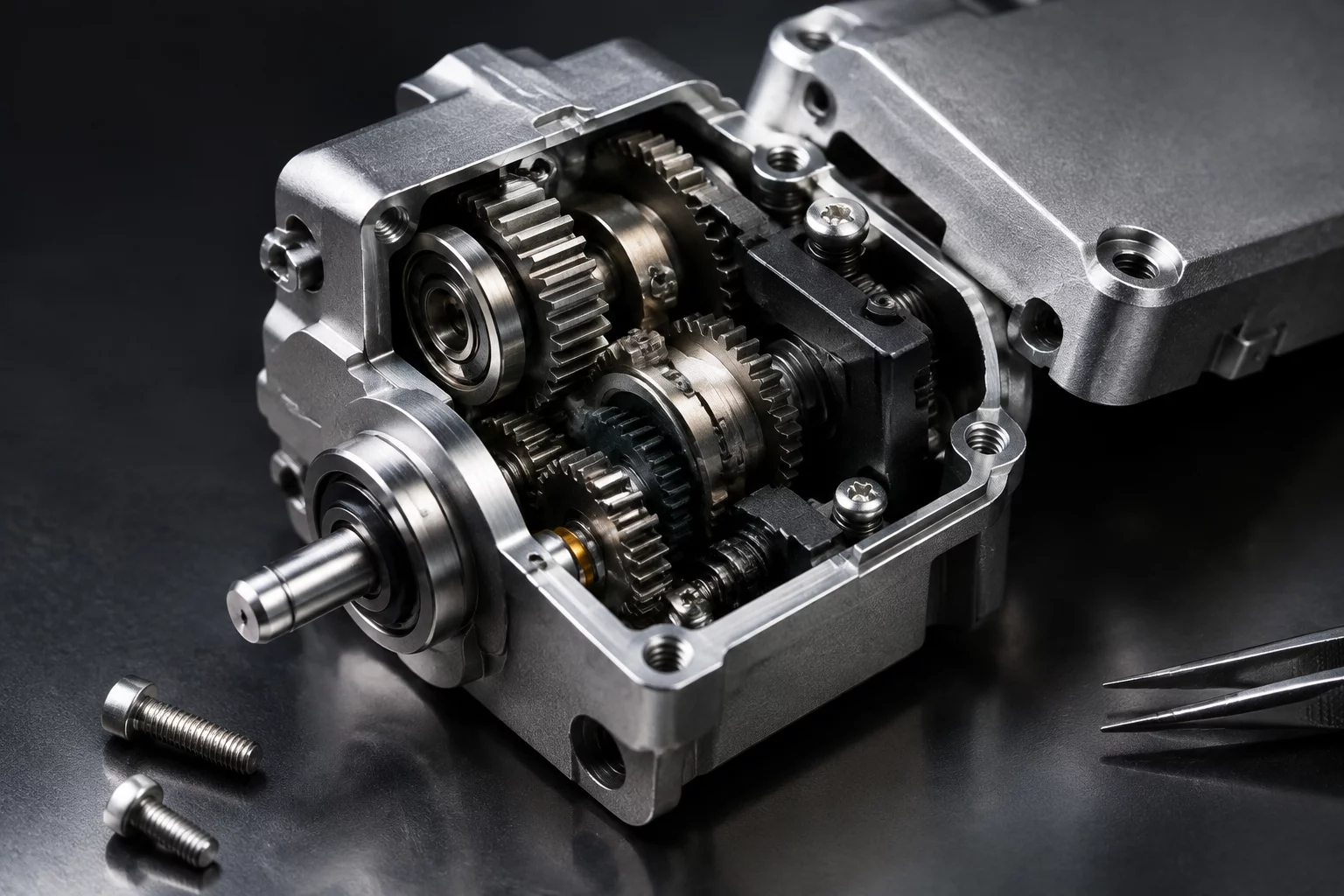
Shifted all primary transmission gears into concentric orbits, reducing outer envelope width by 28% while tightening internal tool clearance.

02
What We Learned

Extreme compactness forces blind fastener insertions during final stage staging, exponentially raising manual assembly cycle time.

03
Convergence Question

Does the 28% space savings justify requiring dedicated magnetic torque bits on the production line?

01
What Changed

Introduced a modular clamshell chassis dividing the mechanical drivetrain into two independent pre-testable sub-assemblies.

02
What We Learned

Assembly time dropped 42%, but joint rigidity requires two additional dowel alignment pins across the parting line.

03
Convergence Question

Can the team tolerate two additional alignment pins to achieve seamless operator assembly?

01
What Changed

Arranged all chassis fasteners on an exterior single-plane perimeter with uninhibited vertical driver approach angles.

02
What We Learned

Field servicing requires no specialized tools, but aesthetic shrouds must increase overall device height by 6mm.

03
Convergence Question

Is standardizing on accessible external hardware worth the 6mm height delta on the desk?

Featured Case Study 2026-08-05 Robert Vance

When a New Requirement Reopens the Design

Discover how an unexpected mid-stage thermal constraint forced an engineering team to revisit two discarded prototype options and merge their spatial architectures.

What Changed

Which Geometric & Structural Decisions Differ

When exploring parallel concept paths, the core architectural value lies in isolating which geometric dimensions, fastener interfaces, and parting lines were modified to test distinct mechanical hypotheses.

Option A Envelope Reduction

Tightly Nested Internal Gearing

Sub-chassis housing volume reduced by 32%. Eliminates standalone bracket mounts in favor of integrated cast wall pockets.

Enclosure Volume: 142 cm?
Parting Line Shift: Z-Axis +14mm
Critical Trade-Off: Zero Tool Clearance
Option B Unidirectional Stack

Single-Axis Top-Down Insertion

All rotational shafts and guide pins mount strictly along the +Z vector, eliminating flip-over steps during final assembly line jigs.

Assembly Vectors: 1 Direction (Z)
Alignment Tolerance: ±0.05 mm
Critical Trade-Off: Increased Base Height
Option C Service Access

Externalized Fastener Flanges

Relocates all primary structural M3 torx screws outside the sealed internal cavity, allowing maintenance access without casing teardown.

Tool Reach Angle: 90° Direct
Fastener Count: 6 Screws (Standard)
Critical Trade-Off: External Perimeter +18%
Methodological Reference Structuring Full Option Forks

How to isolate variables and compare parallel physical models without losing track of baseline criteria.

Evaluation Phase • Step 04

Trade-Off Questions & Compromise Mapping

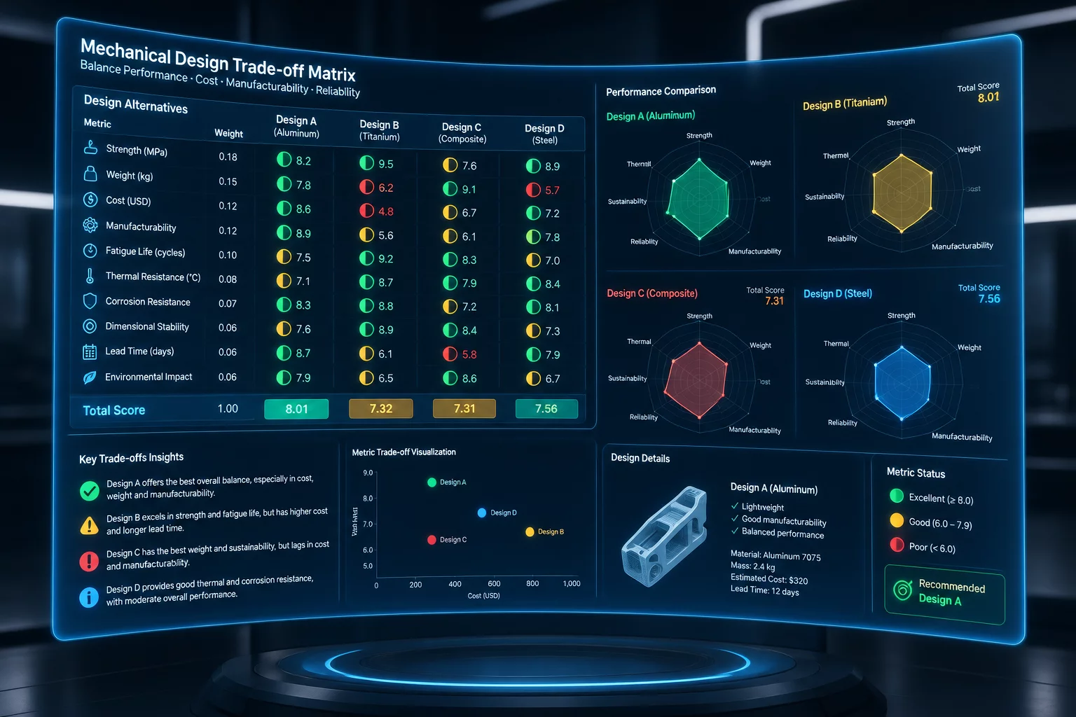
Every mechanical variation solves one specific bottleneck while generating a new physical constraint. Parallel engineering explores what improved versus what secondary compromises appeared before committing tooling.

Option A • Volume Reduction

Ultra-Compact Envelope Path

Starting Baseline
240 cm? Target Volume
What Improved:

32% overall envelope reduction and reduced weight by shifting bearings inside the motor collar.

Compromise Appeared:

Blind internal fasteners require custom hex key extension and increase final assembly step duration by 4 minutes.

Convergence Question

Does the footprint reduction justify the secondary tooling cost for assembly jigs?

Option B • Assembly Sequence

Top-Down Direct Access Path

Starting Baseline
Z-Axis Fastener Insertion
What Improved:

100% top-accessible fastener layout enabling single-operator assembly without fixture flipping.

Compromise Appeared:

Requires 2 additional structural ribs to maintain torsional stiffness, adding 65g of aluminum mass.

Convergence Question

Can the added structural mass be tolerated within the overall payload budget?

Option C • Part Consolidation

Monolithic Unibody Bracket Path

Starting Baseline
8 Disjointed Sub-Parts
What Improved:

Eliminated 7 fasteners, 2 alignment pins, and all tolerance stack-up across mating faces.

Compromise Appeared:

5-axis CNC machining setup required, elevating prototype per-unit production cost by 40%.

Convergence Question

Is production volume high enough to offset upfront tooling and machine-hour rates?

Related Methodology 2026-08-03 William Hayes

CONVERGENCE POINTS & DECISION GATES

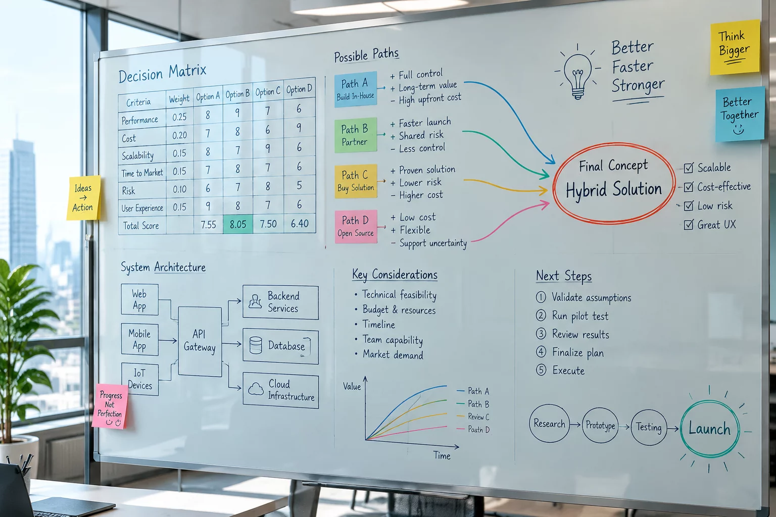
Knowing when to stop diverging is as vital as exploring alternatives. An engineering team should converge only when parallel option forks have exposed the hidden failure modes, assembly sequences, and physical constraints required to make an informed commitment.

CONVERGENCE CRITERIA MATRIX INTERACTIVE GATE SELECTOR

Signal: New Revisions Yield Diminishing Learning

Exploration has reached saturation when additional CAD tweaks or quick test prints confirm previously discovered mechanical behaviors rather than uncovering novel trade-offs.

  • All 3 parallel forks have documented unambiguous failure limits.
  • Tolerancing and thermal clear paths no longer present unmodeled unknowns.
  • The core trade-off between stiffness, weight, and volume is clearly quantified.

Signal: One Primary Constraint Eliminates Alternate Paths

When a hard thermal envelope, motor torque limit, or spatial boundary proves insurmountable for two forks, the viable design path becomes mathematically constrained.

  • Option A exceeds the maximum allowable package volume by >15%.
  • Option C requires exotic materials outside prototype lead-time budgets.
  • Option B satisfies the primary starting constraint without secondary trade-off compromises.

Signal: Assembly Feasibility Precludes Theoretical Benefits

A concept may deliver superior compactness on CAD, but blind fastener driving and nested part dependencies during physical assembly force convergence onto accessible geometry.

  • Physical hand clearance and tool driver angles verified on 1:1 rapid prints.
  • Part mating orientation requires zero blind blind-press operations.
  • Maintenance disassembly cycle takes under 4 operational steps.

Signal: Prototype Learning Merges into Final Tooling Path

The convergence moment occurs when lessons learned from abandoned options are synthesized into a consolidated unibody or low-part-count production setup.

  • Draft angles and parting lines validated against chosen manufacturing process.
  • Secondary operations (tapping, reaming, EDM) reduced to standard tooling.
  • Archived learning logs stored for future redesign cycles.
01

PARALLEL BRANCHING

Develop options A, B, and C with deliberate divergence to isolate specific structural variables rather than whole-system revisions.

02

EVALUATION MATRIX

Measure each fork not by aesthetic preference, but by the tangible failure modes and manufacturing trade-offs it teaches the engineering squad.

03

KNOWLEDGE RETENTION

Archive discarded forks with explicit notes on why they stopped, preserving crucial engineering context when future requirement changes occur.

ABANDONED PATHS [ ARCHIVE REF // 04-DISCARDED ]

THE VALUE OF UNUSED ENGINEERING OPTIONS

When a parallel design concept is retired, it does not represent wasted prototyping time. Structured design forks document critical failure boundaries, establish trade-off baselines, and prevent teams from repeating redundant mechanical experiments.

INSIGHT 01

BOUNDARY DISCOVERY

Testing an extreme packaging constraint reveals the physical threshold where assembly tolerances collapse, establishing safe clearance limits for the active configuration.

INSIGHT 02

PREVENTS CIRCULAR DEBATE

Clear records of why a concept was shelved stop downstream stakeholders from suggesting previously tested and invalidated mechanical routes late in production.

INSIGHT 03

MODULAR REUSE

An abandoned overall architecture often yields isolated snap-fit joints, linkage geometries, or fastener access channels that integrate smoothly into future assemblies.

INSIGHT 04

DEFENSIBLE CONVERGENCE

Choosing a final design path is only defensible when juxtaposed against real, quantified physical trade-offs rather than speculative assumptions.

Communicating Findings to the Team
CASE STUDY ARCHIVE
PARALLEL DESIGN 2026-07-25 Amanda Cole

COMMUNICATING FINDINGS TO THE TEAM

How cross-functional engineering teams synthesize the learnings from rejected prototypes, translate geometric compromises into shared team knowledge, and build consensus around final production commitments.

Full Option Forks

Documented Engineering Forks

Examine real engineering dilemmas where parallel concept branches helped prototype teams learn critical trade-offs before committing to irreversible manufacturing decisions.

CORE EXPLORATION GUIDES

Foundational methods for managing concurrent CAD branches, validating isolated design hypotheses, and extracting structured engineering intelligence before final convergence.

Managing Parallel Concepts Exploration Phase
2026-09-11 • Sarah Jenkins

Managing Parallel Concepts

Protocols for maintaining branch synchronization, version separation, and preventing premature configuration lock-in.

Documenting What Changed Synthesis Phase
2026-09-02 • David Ross

Documenting What Changed

Frameworks for capturing geometric shifts, assembly clearances, and interface impacts across divergent concept paths.

Explore All Parallel Design Methodologies
Review additional guides on decision trees, team alignment, and archiving paths.
Parallel Methodology Counseling

Structure Your Concept Forks

Stuck prematurely converging on a single CAD architecture? Book a focused engineering advisory session. We help mechanical teams structure parallel concept paths, isolate critical unknowns, and formulate clear convergence criteria.

Constraint Isolation Define the exact geometric or assembly constraint driving your branch.
Knowledge Extraction Map what each prototype variant will teach before cutting metal or printing.
Disciplined Convergence Establish rigorous trade-off criteria to merge lessons into the final release.
Standard initial session: 45-minute technical review

Request Engineering Session

Submit your team's current development bottleneck and explore parallel concept pathways.