The Geometric Conflict Behind the Form Factor
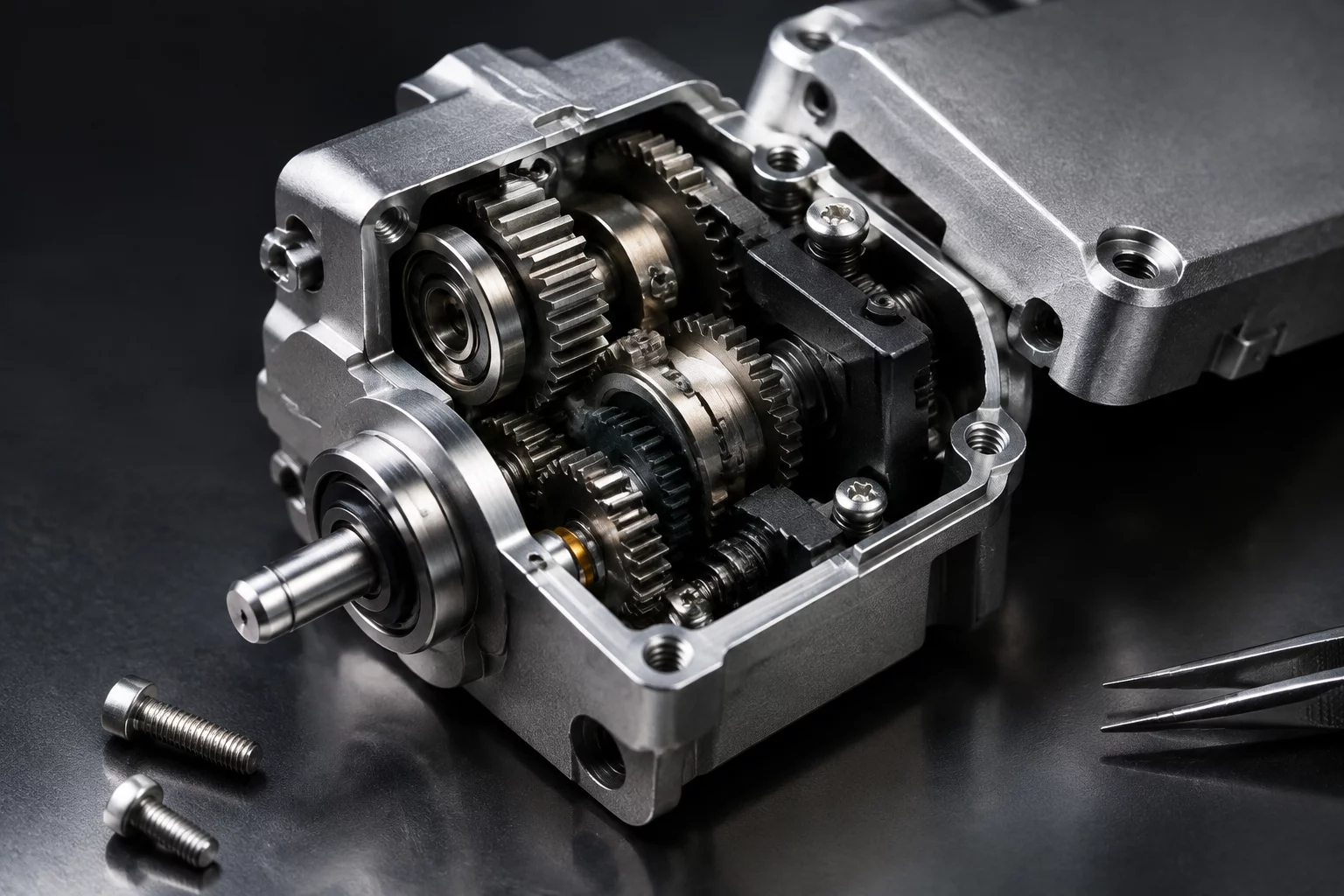
Engineering teams frequently encounter pressure to reduce outer envelope dimensions to satisfy industrial design and user portability goals. In this project, the team committed to reducing the chassis volume by 28%, compressing internal drive modules and power distribution into a single cavity. While the digital CAD model verified nominal zero-interference between components, it neglected tool trajectory envelopes and human finger reach required during manual bench assembly.
The secondary challenge emerged at the interface between the structural mid-frame and the primary reduction gearbox. To eliminate external seam lines, the fasteners were relocated to the interior face of the chassis. Technicians were forced to install M2.5 screws using micro-angle drivers through a narrow 8mm gap, turning a routine five-second operation into a delicate two-minute balancing act prone to cross-threading.
Shrinking the enclosure without expanding tool clearance turns what looks like an elegant CAD model into a manufacturing nightmare on the shop floor.
As production ramp approached, scrap rates spiked due to stripped threads and damaged flexible printed circuits (FPCs). The team needed to step back and evaluate parallel concept branches rather than forcing workarounds onto an inherently constrained physical layout.
Three Design Forks Evaluated to Relieve Assembly Friction
Rather than making incremental band-aids to the congested housing, the team established three distinct option branches to investigate whether volumetric efficiency could coexist with reasonable assembly throughput:
Snap-Fit Sub-Chassis
Replaced internal threaded fasteners with cantilever snap-joints on a glass-filled nylon inner carriage, reducing screw count from 12 to 4.
Split-Clamshell Architecture
Divided outer housing into symmetrical bilateral halves, opening 180-degree bilateral access for linear pick-and-place automated assembly.
Asymmetric Envelope Expansion
Added a 3.5mm strategic localized draft angle along the non-gripping spine, restoring full vertical screwdriver access without altering palm feel.
Testing showed that while Branch Alpha reduced screw count, high tool wear on cantilever tooling raised initial mold tooling capital. Branch Gamma proved optimal, recovering 90% of assembly ease with less than a 4% perceptible change to the exterior envelope.
Quantitative Impact on Production Metrics
Comparing the original ultra-compact layout against the converged Branch Gamma revealed stark differences in cycle efficiency and quality control across production batches:
- Baseline Assembly Duration: 4 minutes 18 seconds per unit with high operator fatigue
- Converged Assembly Duration: 1 minute 52 seconds per unit with zero blind fastening
- Fastener Access Clearance: Expanded from 8mm restricted channel to 22mm direct line-of-sight
- First-Pass Yield Rate: Increased from 81.4% to 98.6% by eliminating FPC pinch points
This case underscores why Design for Manufacturing (DFM) must evaluate tool approach vectors and human ergonomics simultaneously with geometric volume reduction.
Frequently Asked Questions About Compact Assembly
Standard static interference checks only test whether solid parts occupy the same coordinates. Unless explicit tool sweep volumes and hand manipulation envelopes are modeled as dynamic keep-out zones, CAD models easily hide severe access restrictions.
No. By redistributing volume to the rear spine where user hand contact was minimal, the device maintained its slim front profile and perceived lightness while providing the required tool clearance.
Snap-fits excel when annual production volume justifies higher upfront injection tooling cost and when internal components do not require frequent field disassembly for maintenance or calibration.
Have a Question or Case Reflection?
Share your thoughts on assembly clearance trade-offs, ask technical questions, or connect with our mechanical engineering editorial team.
Related Engineering Case Studies
 Exploration
One Constraint, Three Mechanical Concepts
Exploring three divergent structural approaches under a single rigid dimensional constraint.
 DFM Analysis
The Alternative That Simplified Manufacturing
How consolidating multi-part brackets into a single machined unibody slashed cycle times.
 Architecture
Comparing Access, Size, and Part Count
A trade-off study evaluating port access dimensions against internal component partition counts.