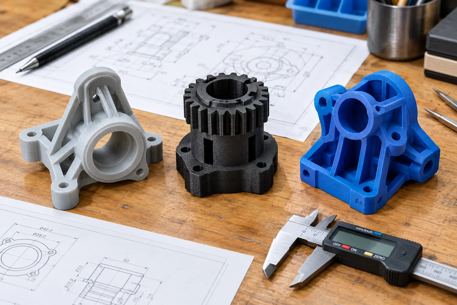
Isolating the Non-Negotiable Boundary
Engineering projects often encounter moments where packaging requirements clash with torque output expectations. In our compact robotic articulation project, the external physical boundary was frozen at a strict 45mm outer cylindrical diameter with a total axial length under 62mm. Rather than immediately selecting a default planetary gear system and tweaking teeth profiles to fit, we formulated the constraint as a clean baseline for parallel exploration.
The primary risk of linear development is fixation on the first viable concept. When engineers squeeze a traditional topology into tight dimensions, secondary issues like bearing load limits, thermal expansion, and assembly blind spots quickly escalate into late-stage redesigns.
Freezing the constraint while multiplying the conceptual branches allowed our team to test fundamental physics rather than patching compromises.
By defining the exact torque load of 28 Nm at 40 RPM as our target metric alongside the 45mm envelope, we established the sandbox. Any concept meeting these two non-negotiable boundaries advanced directly to CAD parametrization and physical 3D-printed layout testing.
Diverging into Three Distinct Mechanical Architectures
Instead of iterating sequentially, we branched the project into three distinct mechanical concepts, each leveraging a completely different load-transfer mechanism within the identical 45mm envelope:
2-Stage Micro Planetary
High manufacturability with standard spur gears, but exhibited significant needle bearing stress under shock loads and required tight coaxial tolerances.
Integrated Cycloidal Drive
Exceptional shock resistance and zero backlash potential; however, eccentric balancing and custom pin-ring machining increased early unit cost.
Cup-Style Strain Wave
Minimal part count and unmatched compactness, but presented high friction at low operating temperatures and required specialty flexible cup tooling.
Each branch was maintained as an independent model branch in our cloud CAD environment. This prevented cross-contamination of feature trees while allowing direct mass property and stress distribution comparisons across identical boundary envelopes.
Quantitative Comparison and Convergence Decision
After 10 days of parallel finite element analysis and rapid FDM/SLA prototype validation, clear structural differences emerged across the three mechanical pathways. We scored each architecture against assembly ergonomics, thermal dissipation, peak torque capacity, and component count:
- Torque Density Winner: Integrated Cycloidal Drive achieved 29.4 Nm without tooth deflection failure during shock tests.
- Assembly Simplicity: Strain Wave utilized 14 total components, compared to 38 in the Micro Planetary and 24 in Cycloidal.
- Thermal & Efficiency Benchmark: Micro Planetary yielded 94% efficiency at nominal speed, whereas Strain Wave fell to 78% under cold-start conditions.
- Final Convergence Selection: The team converged on the Cycloidal architecture, adopting modified pin-bushing retention developed during Concept Alpha testing.
The true value of parallel exploration manifested during convergence: elements from the discarded planetary concept (specifically the input bearing preloading method) were grafted directly into the cycloidal assembly, producing a hybrid solution that neither branch would have found on its own.
Frequently Asked Questions
Sequential prototyping creates psychological anchoring to the first workable prototype. Parallel branching forces objective scoring against identical boundaries simultaneously, saving cumulative engineering cycle time.
We utilized top-down skeleton modeling where the 45mm outer bounding cylinder and mounting interface points were linked as immutable references, while the internal gear kinematics lived in isolated branches.
Both the Micro Planetary and Strain Wave models were version-tagged, fully annotated with failure mode analyses, and archived in our design repository for future low-torque projects.
Discuss Actuation & Concept Trade-Offs
Have a complex packaging boundary or multi-concept mechanical problem? Share your project details with our engineering research team.
Related Engineering Case Studies
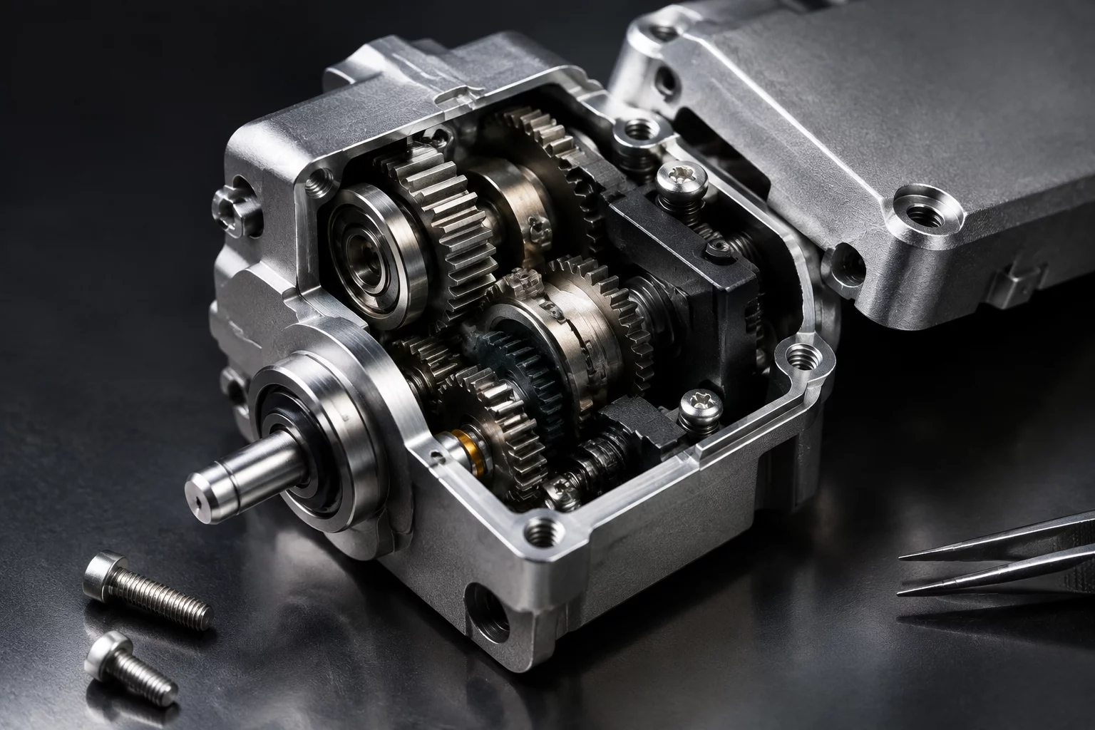 Assembly
The Smaller Design Created a Harder Assembly
An in-depth teardown of how minimizing component envelope led to unexpected hand-tool clearance bottlenecks during production.
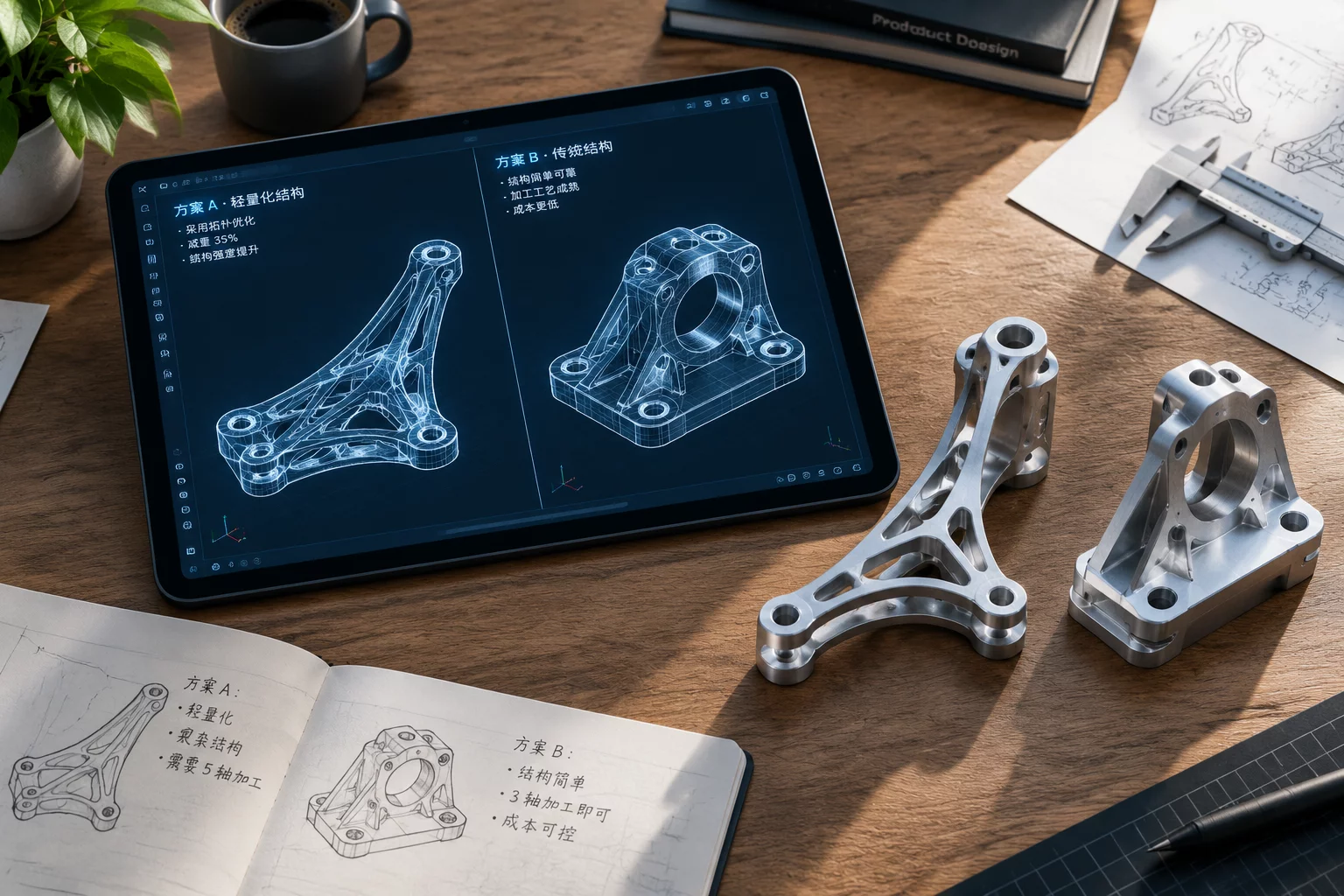 Decision Making
When Two Good Ideas Solve Different Problems
Resolving engineering conflicts when parallel concept branches solve distinct, competing performance requirements.
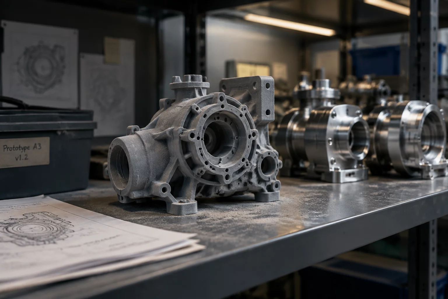 Knowledge Base
Why an Abandoned Option Still Matters
How recording early mechanical dead ends and discarded prototype geometries prevented repeat engineering errors later.