
The Mechanical Dilemma: Clearance Envelope vs Component Count
When optimizing an enclosure or structural chassis for manufacturing, teams frequently pursue part count reduction as a primary metric. Consolidating sheet metal brackets or injection-molded ribs into a single unibody shell reliably lowers raw material logistics and nominal vendor line items. However, severe geometric consequences emerge inside the assembly envelope as perimeter walls become monolithic.
In this investigation, the initial design collapsed four separate chassis plates into a single deep-drawn unibody enclosure. While this move cut eleven individual fasteners from the bill of materials, the remaining internal mounting points required a 90-degree offset torque driver with less than 12 millimeters of vertical clearance. Technicians spent disproportionate cycle time guiding hardware blindly into internal bosses.
A consolidated chassis that cuts ten screws looks brilliant on a cost spreadsheet until assembly floor yield drops because screwdrivers cannot achieve perpendicular torque.
To evaluate these trade-offs systematically, the team established three parallel concept branches. Each concept balanced aperture size, internal tool clearance corridors, and structural component quantities under realistic line assembly conditions.
Branching Concepts Across Three Parallel Architectures
Rather than making small incremental tweaks to a single CAD model, three distinct enclosure approaches were modeled and tested in parallel to capture real assembly metrics:
Monolithic Unibody
Minimal 8-part count with single deep access port. Required specialty ball-end hex drivers and tight internal maneuvering.
Split Dual-Clamshell
14-part count featuring wide-open 120 mm clearance windows, allowing standard vertical pneumatic tool insertion.
Modular Service Hatch
19-part count utilizing secondary stamped maintenance bezels to isolate high-wear wear components from the main chassis.
Physical 3D printed iterations and physical mockups allowed the team to measure actual seconds per fastener, screw strip rates, and operator ergonomics across every variant before finalizing production tooling.
Convergence Decision & Measured Metrics
Quantitative testing verified that Option B provided the ideal balance. While Option B increased nominal part count by six structural components compared to Option A, it eliminated the need for specialized tooling fixtures and dropped the total assembly duration by more than a third.
- Fastener Accessibility: 100% line-of-sight clearance achieved for standard powered torque drivers.
- Assembly Cycle Time: Reduced from 4 minutes 18 seconds (Option A) down to 2 minutes 40 seconds (Option B).
- Fastener Commonality: Standardized 100% of internal threads on M3 socket button-head screws.
- Field Serviceability: Technicians can access sub-modules without removing primary load-bearing stiffeners.
This convergence demonstrates why aggressive part-count minimization must always be cross-referenced against realistic assembly kinematics and tool clearance envelopes.
Frequently Explored Questions
Eliminating parts often forces remaining components to have more complex geometry, which can restrict internal tool clearance, complicate assembly sequences, and drive up labor costs more than the bill of materials savings justify.
Engineers typically combine the driver bit diameter, tool head length, screw lead-in length, and a minimum 15 to 25 millimeter perimeter envelope for operator hand clearance or automated fixture alignment.
Building physical 3D prints of opposing access approaches side-by-side reveals ergonomic snags and torque tool collisions that digital CAD clash detection frequently misses.
Submit Your Mechanical Case Scenario
Discuss your team's current assembly clearance challenges or get feedback on trade-off evaluations from the OptionFork engineering group.
Related Engineering Case Studies
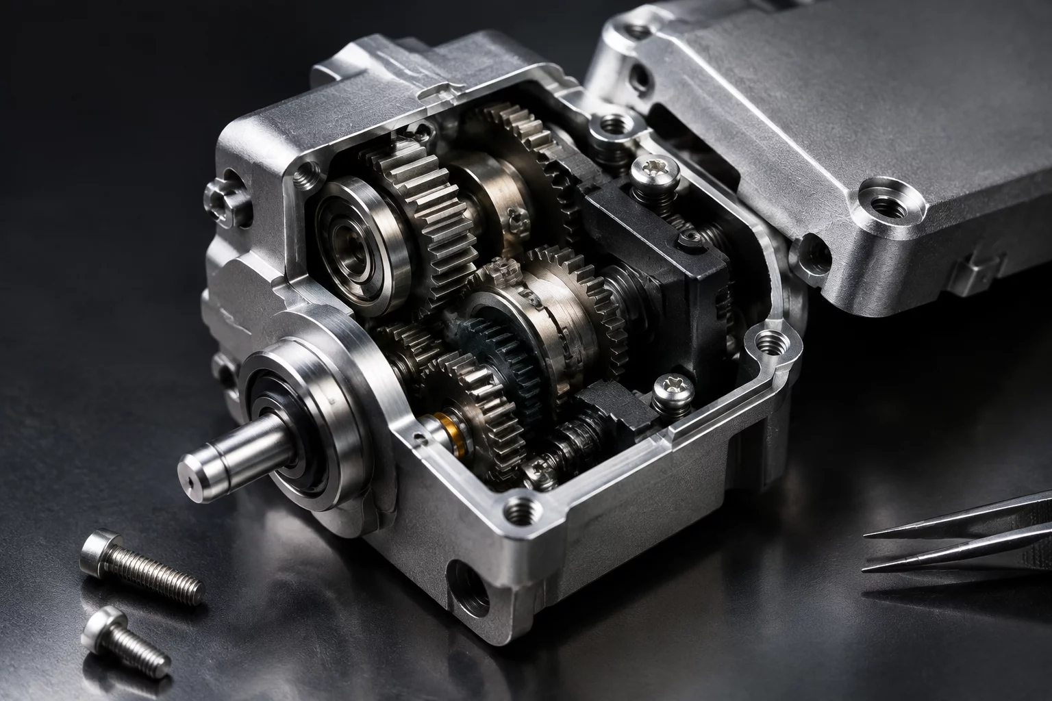 Assembly Analysis
The Smaller Design Created a Harder Assembly
How aggressive enclosure volume reductions complicated interior gearing access and tooling trajectories.
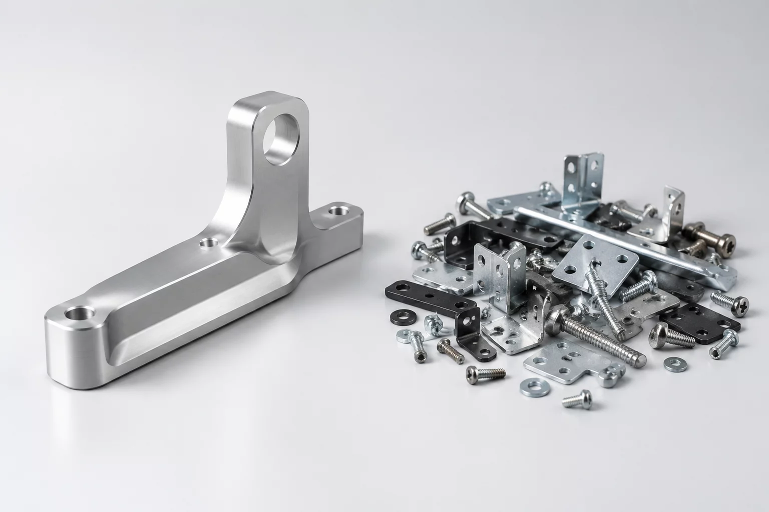 DFM Optimization
The Alternative That Simplified Manufacturing
Substituting a complex welded assembly with a single CNC-milled unibody to slash production bottlenecks.
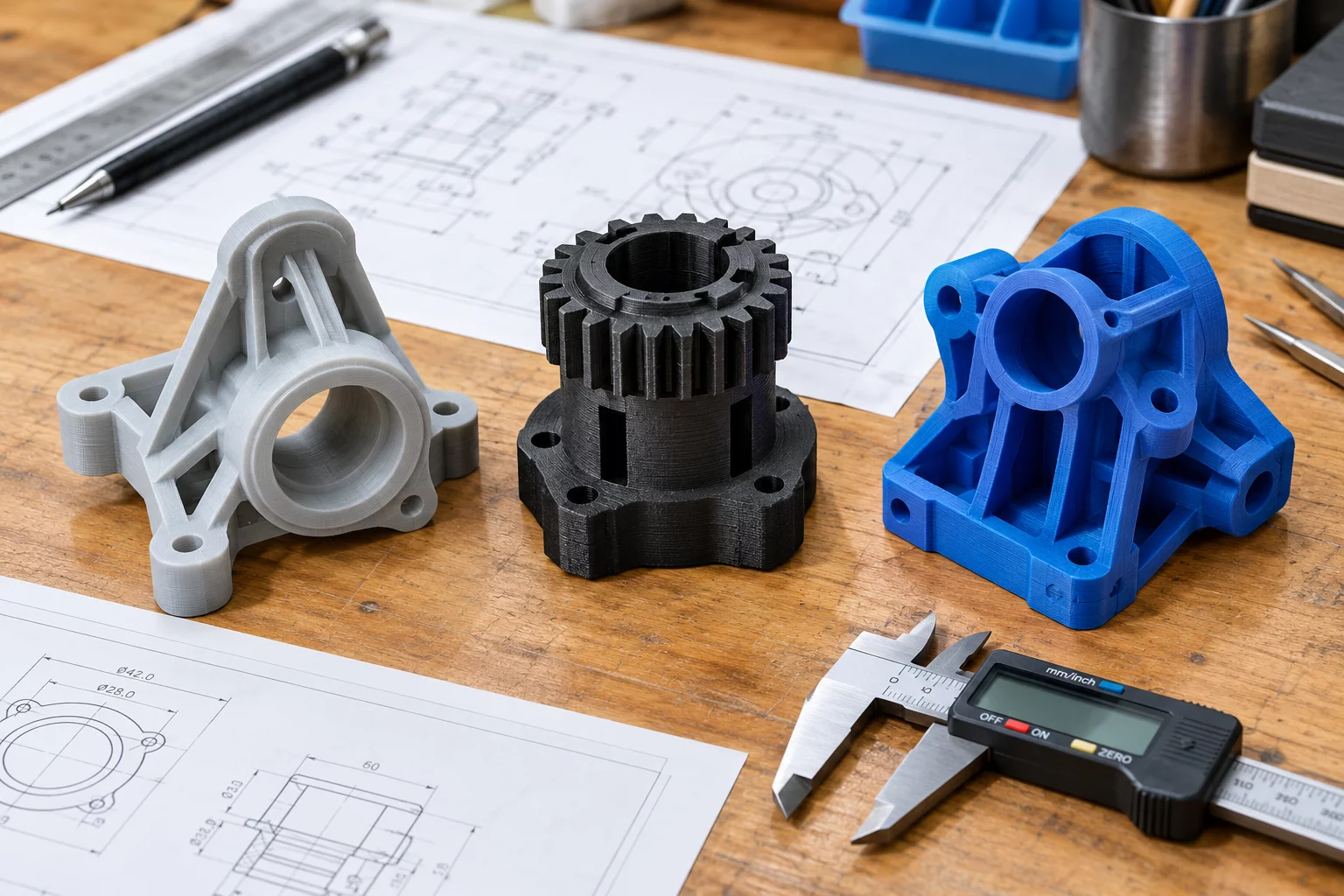 Parallel Exploration
One Constraint, Three Mechanical Concepts
Exploring how a fixed spatial bounding envelope yielded three radically different kinematic load mechanisms.