The Option Fork Framework
A structured engineering methodology to branch parallel CAD concepts, isolate high-risk parameters, and make evidence-backed convergence decisions.
Isolating Variables Through Disciplined Concept Branching
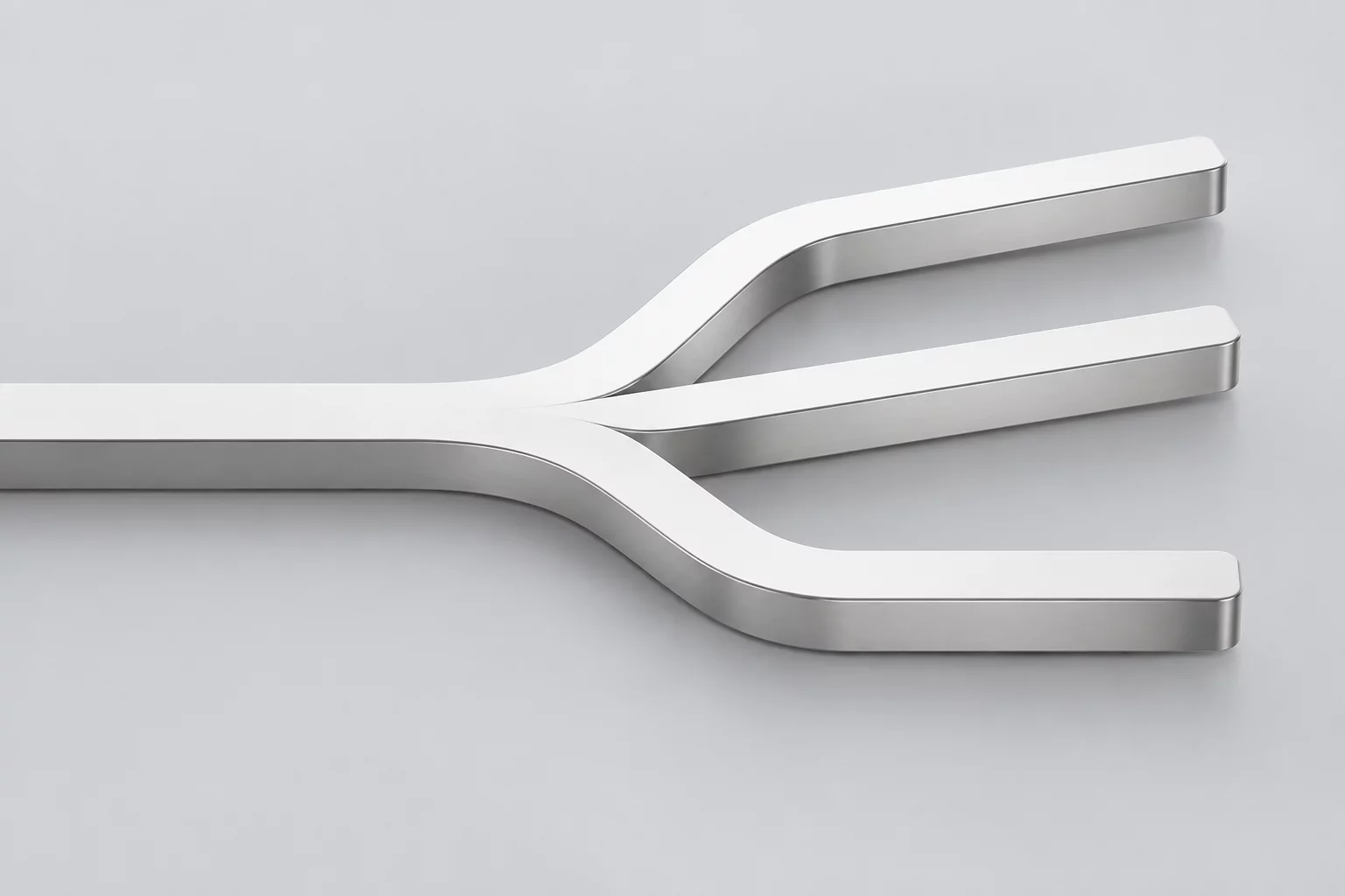
Hardware development teams frequently commit to a single mechanical topology before fully mapping out clearance envelopes, thermal dissipation paths, or robotic assembly access. The Option Fork Framework introduces an intentional branching protocol where two to four parallel concepts are advanced simultaneously under identical interface constraints. Rather than relying on speculative debates in design reviews, engineers construct functional CAD branches to test divergent hypotheses against hard manufacturing data.
Each fork isolates a distinct structural strategy—such as an integrated unibody housing versus a multi-piece modular frame. Developing these alternatives concurrently for a bounded evaluation cycle prevents premature design lock-in, exposes hidden assembly bottlenecks early, and gives the team empirical benchmarks to justify the final convergence direction.
Every mechanical fork must test a mutually exclusive design hypothesis within identical boundary conditions to produce objective, quantifiable trade-off data.
Run an Option Fork on Your Sub-Assembly
Consult our engineering team to review branching criteria, constraint boundaries, and convergence scoring matrices for your hardware project.
The Four Core Operational Phases of an Option Fork
Disciplined exploration requires strict schedule bounds to prevent parallel design efforts from turning into unchecked scope expansion. The framework divides concept development into four actionable phases:
- Boundary Pinning: Locking all external datum surfaces, keep-out zones, and electrical interfaces before initiating parallel branches.
- Divergent Modeling: Building separate internal architectures in isolated CAD workspaces to directly compare fabrication feasibility and component density.
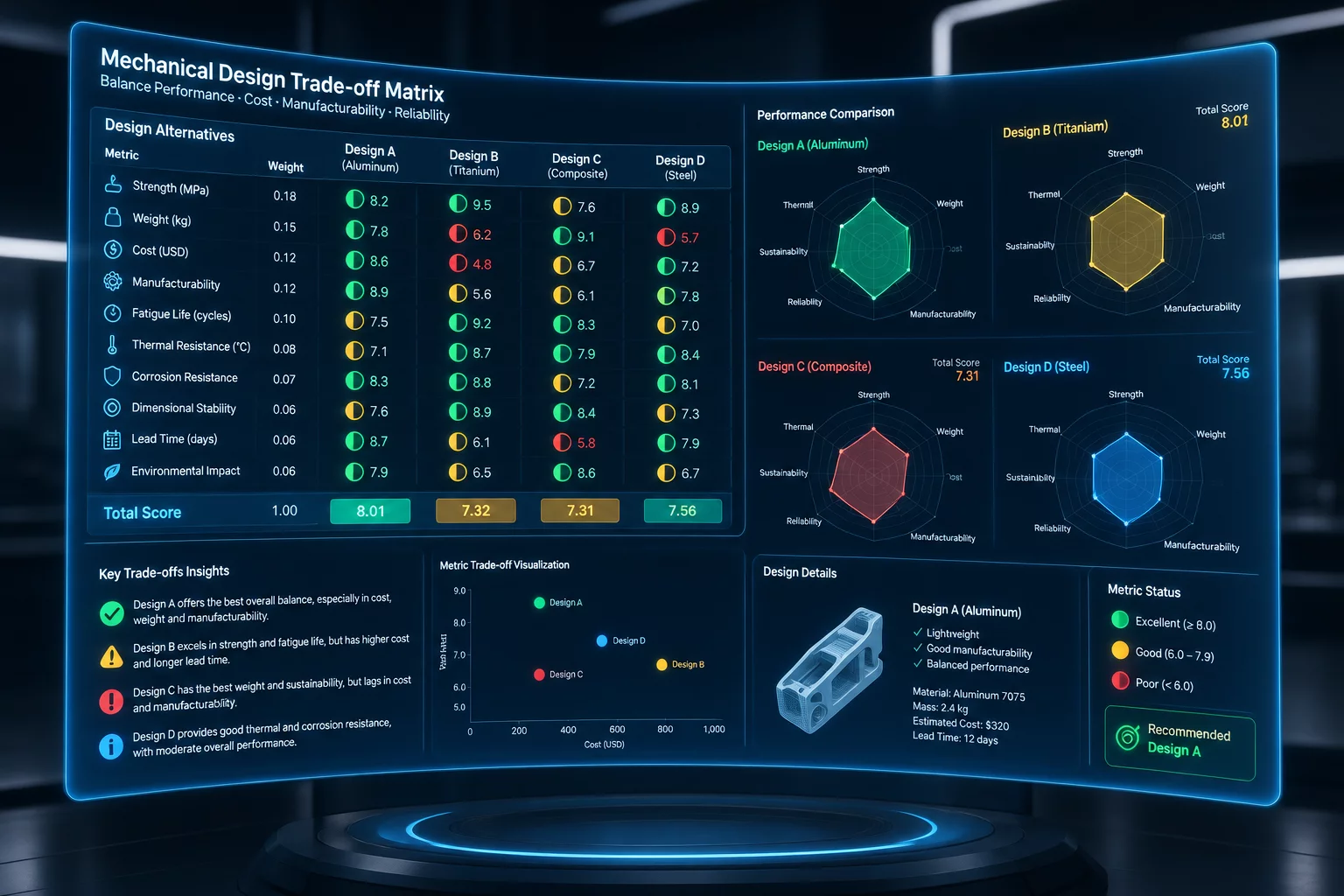
- Matrix Scoring: Evaluating each variant against a weighted matrix covering part count, assembly time, tooling investment, and structural rigidity.
Once the evaluation threshold is reached, the team conducts a formal convergence review. The selected path frequently incorporates refined sub-features discovered during the exploration of discarded options, while all retired CAD models are permanently documented with failure notes to prevent repeated mistakes in subsequent revisions.
Framework Implementation Protocols & FAQs
Initiate a fork whenever a primary functional requirement—such as thermal management or structural deflection—can be satisfied by multiple mutually exclusive topologies. If mathematical estimations cannot decisively resolve the risk, creating bounded parallel models is the most cost-effective path.
Parallel branches should strictly run for one to two sprint cycles, typically 7 to 10 working days. Keeping branches open beyond the initial prototyping stage creates divergence debt, increases synchronization overhead, and fragments the engineering team's focus.
Abandoned branches are frozen in version control and tagged with a concise convergence summary detailing why they were retired. Preserving this institutional knowledge prevents future engineering cycles from re-exploring dead ends when team members change or requirements evolve.
Apply This Methodology to Your Project
Submit your sub-assembly challenges or design constraints to receive structured guidance on setting up parallel CAD branches and trade-off matrices.