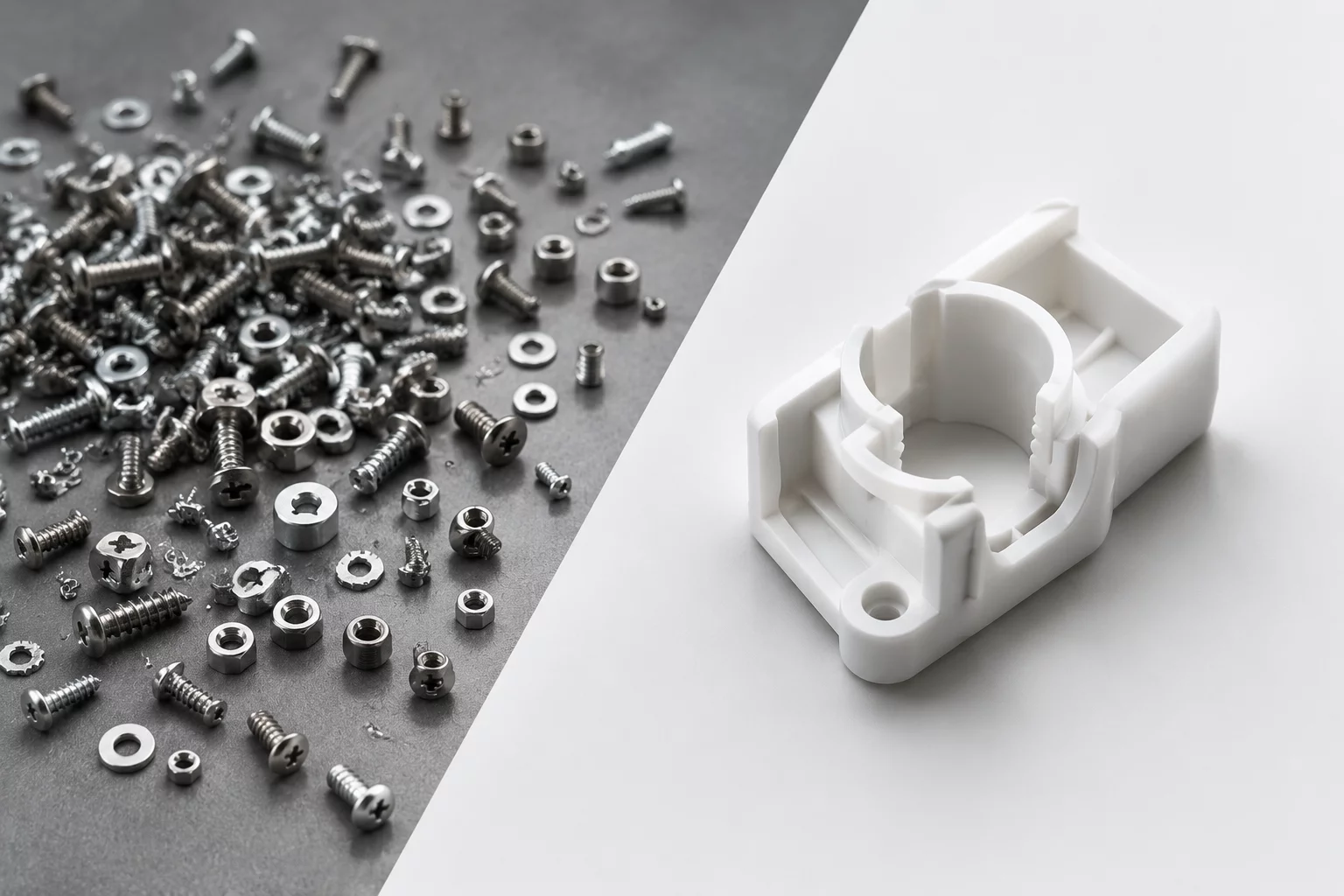
Component Orientation Optimization
Evaluating multi-axis spatial alignment to reconcile structural stiffness, CNC tool paths, draft clearances, and insertion ergonomics before freezing mechanical envelopes.
The Spatial Orientation Bottleneck in Concept Branching
In preliminary mechanical design, assigning orientation to internal brackets, power modules, and kinematic linkages often happens by habit rather than methodical calculation. When engineers fix an orientation prematurely, downstream tooling costs and assembly friction compound rapidly. Rotating a core sub-assembly by merely forty-five or ninety degrees alters structural load transfer, modifies mold draw directions, and transforms line-of-sight fastener clearances.
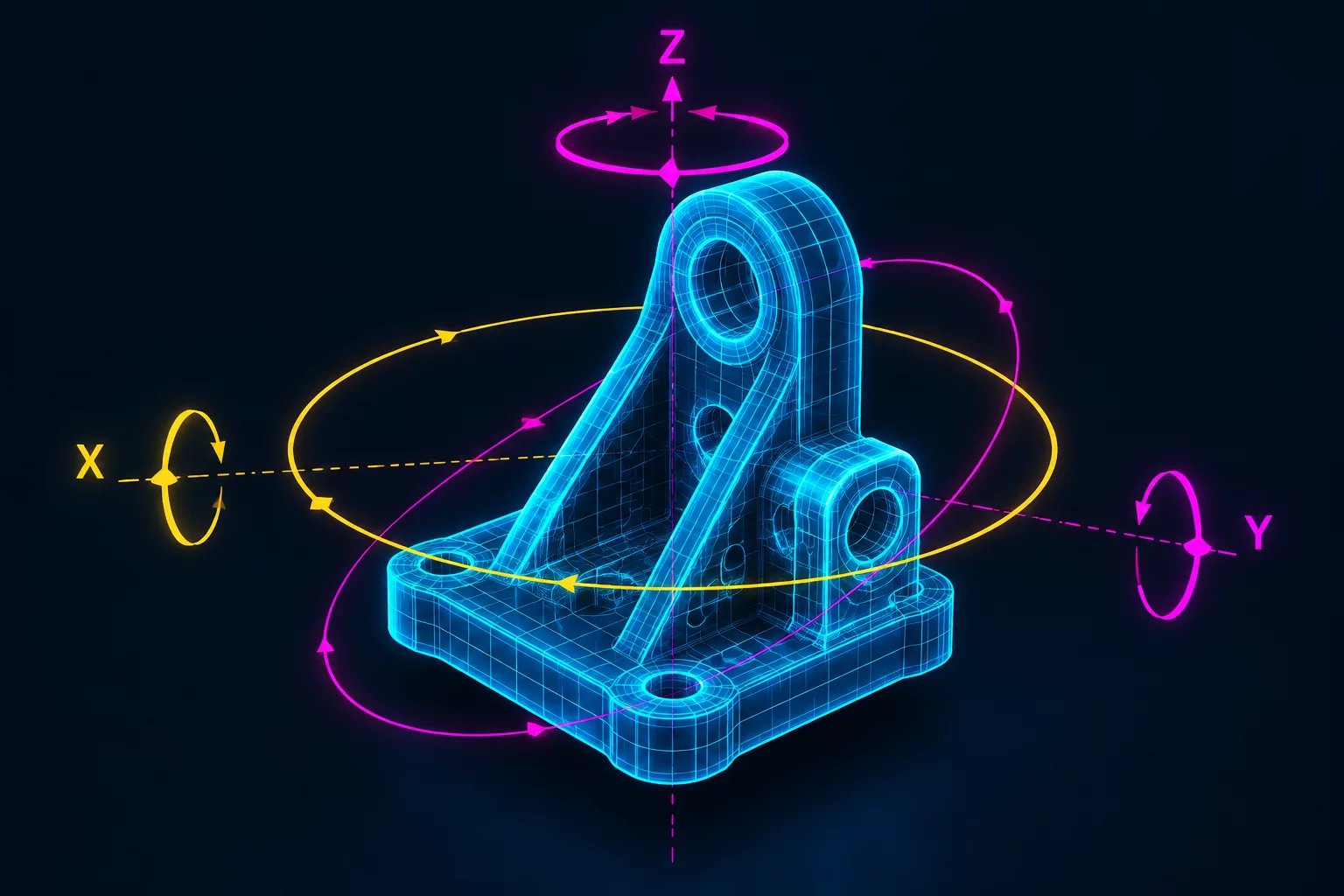
Our Component Orientation Optimization methodology systematically decomposes the part coordinate system along three competing engineering vectors: primary force distribution, primary manufacturing access, and primary assembly insertion. By benchmarking candidate orientations inside parallel CAD branches, engineering squads reveal non-obvious arrangements that cut tooling complexity without compromising mechanical integrity.
Never lock a part's coordinate system to the global chassis envelope before auditing how rotational variance impacts 3D print layer strength, milling setup counts, and blind technician insertion.
Orientation Scoring Worksheet
Download the matrix used to calculate rotation penalty points across fabrication, thermal dissipation, and fastening access.
Core Evaluation Vectors for Orientation Optimization
Applying orientation optimization requires teams to grade every candidate spatial arrangement against rigorous physical and operational metrics:
- Structural Load Alignment: Ensuring anisotropic grain structures, 3D print layer seams, or extruded fiber vectors directly counter peak tensile and shear stresses.
- Single-Axis Tooling Clearance: Aligning parting lines, mold pull directions, and CNC bit approaches along a unified datum to eradicate costly side-actions and 5-axis setups.
- Gravity-Assisted Top-Down Insertion: Orienting internal components so manual or robotic assembly operators insert parts strictly along a single downward vertical vector (Z-axis).
When these vectors conflict, the framework prescribes structured trade-off iterations. For example, if rotating an internal cooling plate 90 degrees improves thermal convection by 14% but requires a secondary manual fastening step, the decision matrix computes whether the thermal headroom justifies the cycle time addition.
Step-by-Step Implementation Guide
Isolate the component in a neutral sub-assembly space. Establish functional datums based solely on mechanical contact interfaces and fluid/thermal channels rather than external aesthetics. Identify every rotational degree of freedom that remains unconstrained by mating parts.
Generate distinct design branches representing standard orthogonal rotations (0°, 90°, 180°, 270°) and key angular off-axis alignments. Run automated collision checks, draft angle analyses, and tool sweep simulations across each branch simultaneously.
Score each candidate branch against production volume criteria. For high-volume injection molding, prioritize zero side-action orientations; for low-volume aerospace CNC milling, prioritize minimal fixturing changes and minimal stock material removal.
Apply Orientation Optimization to Your Hardware
Share your mechanical packaging constraints with our engineering team to review parallel CAD rotation models and resolve tooling bottlenecks.