Assembly Sequence Analysis
Evaluating mechanical build hierarchies, fastener access vectors, and collision risks early in the multi-concept CAD exploration phase.
Ordering Mechanical Subassemblies Before Detailed Modeling
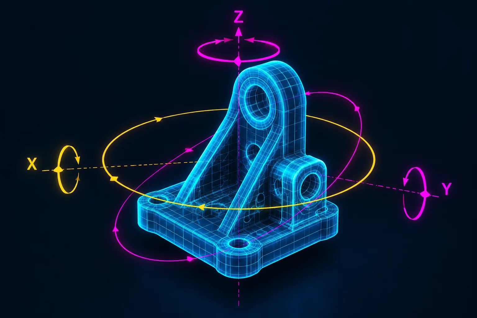
In exploratory mechanical engineering, candidate design concepts often appear pristine in static 3D models until someone traces the chronological steps required to assemble them. Assembly Sequence Analysis systematically inspects whether fasteners, bearings, cable routes, and internal retention clips can be reached by human hands or automated end-effectors without impossible spatial collisions. Evaluating sequence constraints while concepts are still branching prevents teams from investing engineering hours into packaging that looks brilliant on screen but is disastrous on the assembly line.
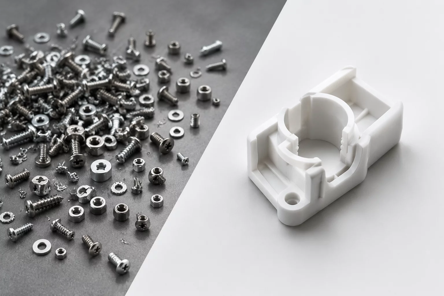
When parallel concepts branch into differing structural architectures, sequence evaluation highlights hidden fabrication friction. A unibody enclosure might eliminate exterior fasteners yet require a precarious blind-insertion process for an internal PCB. Another concept with modular chassis plates may show a slightly higher part count while providing straightforward top-down assembly without specialized tooling. Sequence analysis frames these trade-offs transparently, helping designers converge on robust, buildable hardware architectures.
A concept is only as viable as its least accessible fastener; analyzing assembly sequence dependencies during concept branching eliminates unbuildable packaging before detailing begins.
Sequence Precedence Worksheet
Download our structured template to map part precedence graphs, tool clearance zones, and orientation changes across parallel concepts.

Three Critical Pillars for Sequence Verification
Assessing assembly feasibility across competing mechanical branches relies on evaluating three distinct physical constraints:
- Tool Clearance Envelopes: Verifying line-of-sight and clearance boundaries for torque drivers, allen wrenches, and press-fit fixtures before locking neighboring chassis ribs.
- Monotonic Insertion Vectors: Prioritizing single-axis (Z-direction) stacking that allows components to drop into place without awkward multi-axis gymnastics.
- Field Service & Teardown Access: Confirming that wear components like gaskets, bearings, and filters can be extracted without stripping down unrelated structural modules.
Tracking these pillars across parallel concepts gives engineering teams factual evidence when choosing between compact spatial envelopes and effortless manufacturability.
Step-by-Step Sequence Evaluation Workflow
Map every component as a node connected by directional dependency arrows. If Part B cannot be physically inserted or torqued until Part A is installed, that relationship forms a rigid precedence constraint that defines candidate branch viability.
Simulate swept volumes along each component insertion trajectory in CAD. Highlight interference with adjacent bosses, wire conduits, and chassis walls to ensure no blind interference occurs on the shop floor.
Count how many times an assembly must be turned, flipped, or transferred to different holding jigs. Concepts requiring repeated reorientations accumulate substantial friction scores, guiding final convergence toward unidirectional assembly schemes.
Submit a Framework Inquiry
Looking to evaluate assembly sequence bottlenecks or tool access limits across your active concept variations? Contact our team for targeted methodology guidance.