Parallel Prototyping Guide
Running concurrent physical test models to isolate kinematic risks, reduce tooling uncertainty, and eliminate single-path commitment bias.
Breaking the Trap of Sequential Physical Iteration
Hardware development teams frequently slip into sequential testing habits without recognizing the cognitive trap. Building one prototype at a time feels financially conservative, yet it subtly forces engineers into defending flawed initial geometry simply because substantial fabrication hours were already spent.
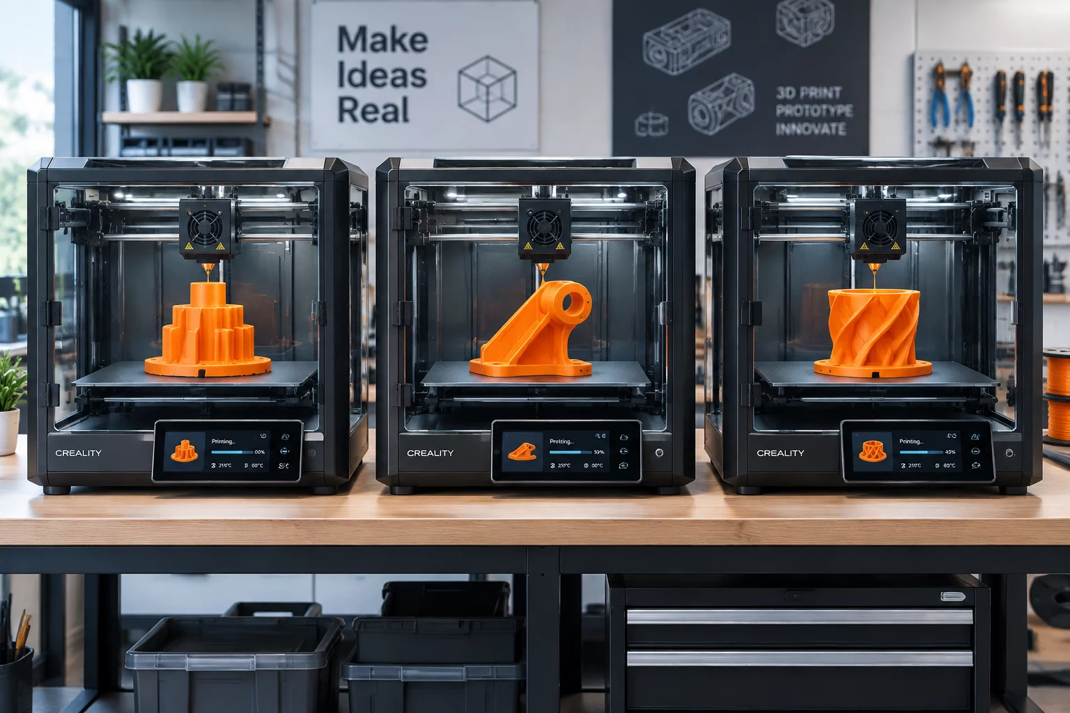
Parallel prototyping replaces this hesitation by creating two to four contrasting physical variations concurrently. By fabricating competing snap-fit geometries, linkage configurations, or modular bracket profiles in the exact same print queue or machining batch, the team shifts its emotional attachment away from a single artifact and onto empirical comparative data.
Fabricating contrasting mechanical variations in parallel cuts emotional bias and reveals non-linear assembly constraints that single-path iterative testing consistently conceals.
Download the Parallel Build Matrix
Access our standardized worksheet for organizing print bed layouts, tolerancing targets, and sensory test criteria across parallel prototype runs.
Structuring Disciplined Physical Comparison Runs
Executing parallel builds successfully requires strict parameter isolation rather than haphazard experimental prints. If every variable changes between iterations, determining which geometric feature produced an observed failure becomes impossible:
- Maintain uniform print orientations, slicer densities, and ambient curing temperatures across all competing test specimens.
- Standardize mounting interfaces and fastener locations so different modular cores can swap into a single master chassis.
- Establish clear quantitative pass/fail thresholds for insertion force, tactile engagement click, and deflection under load before parts leave the build plate.
When three engineers simultaneously handle distinct physical variations side-by-side during an assembly review, subjective debates dissolve into objective kinematic observations. Weak structural ribs and tight clearance pockets show their limitations immediately.
Implementation Stages & Decision Gates
Fork the master CAD model into independent branch variations. Keep all surrounding envelope boundaries static while varying only the core mechanical mechanism, wall thickness, or fastener schema.
Run all variations concurrently using identical material lots. Engrave distinct debossed revision codes (e.g., V-A, V-B, V-C) directly onto the surface to prevent assembly confusion on the shop floor.
Conduct randomized cycle testing and blind ergonomic assessments with team members who did not model the CAD geometry. Record tactile feel, joint play, and assembly cycle time before selecting the winning candidate.
Submit a Prototyping Review Inquiry
Share your current assembly challenge or parallel test configuration with our hardware engineering team for targeted methodology feedback.